Computer Science Project: Wireless Sensor Networks with ZigBee
 Svetozar Stojanovic

Introduction
A couple of years back when I was studying computer science at the Frankfurt University of Applied Sciences, I picked the project module Wireless Sensor Networks with ZigBee offered by Professor Krauße.
It all seemed right up my alley, as it had:
- real hardware on which codebase can be tested on and
- sensors that may mimic real life application.
This team project comes in two varieties, the one I signed up for was utilizing BNO055 smart sensor combining accelerometer, gyroscope and magnetometer of which we only used the gyroscope. Our application was reading both Euler and Quaternion values from the sensor and visualizing the breadboard along with the ZigBee development board on the screen via VPython (Visual Python). These two requirements were mandatory but to impress our peers from other teams my personal touch for visualization is developing a maze game with ball trying to escape (controlled by the sensor), each time with a randomly generated maze.
The BNO055 smart sensor offers gyroscope readings both in Euler angles and Quaternions and we were required to read both of them.
First, let's gloss over the recipe for this project.
Project components
Software
- BitCloud Embedded SW Stack from Atmel Version 3.3.0 (C/C++)
- Python Version 3.8.5
- VPython - Visual Python graphics library Version 7
Hardware
- 3 x ZigBee ATMEGA256RFR2 Radio modules
- 1 x PAN coordinator
- 2 x ZigBee end-devices coupled with BNO055 9-axis sensors
- 2 x Battery packs with 2 AA batteries each (for end-devices)
- 2 x Bosch BNO055 9-axis smart sensors
- 1 x UART bridge
- 1 x USB mini to USB 2.0 cable for connecting with PC
Connection and sensor read/write
The goal was to set up a Personal Area Network (PAN) between ZigBee devices and communicate sensor data from two end-devices through coordinator (master node) to the PC.
The main communication protocol between the ZigBee end-devices and 9-axis sensors on the boards is the Inter-Integrated-Circuit (I2C) or in another name the Two Wire Interface (TWI).
For this project we only had three ZigBee devices in total so the address range could be quite small. Since they each had an 8-bit processor on-board the only option was the 7-bit address range for the devices communicating inside I2C but there is also a 10-bit address range option.
This theoretically means that there could be up to 127 (27-1) devices communicating via I2C connection (at least one master node needs to be present).
The clock/data rate for this connection is chosen to be 125 KB/s as it suffices the speed at which the sensors can be read.
Also to be noted is that we've put all our code (except constants) in a giant app.c file generated by Atmel Studio. In the end, the file was almost 1000 lines of code.
The definition of the I2C connection is summed up using a HAL_I2cDescriptor_t descriptor:
HAL I2C Descriptor
static HAL_I2cDescriptor_t i2cdescriptor={ .tty = TWI_CHANNEL_0, .clockRate = I2C_CLOCK_RATE_125, .id = BNO055_I2C_ADDRESS, }
Reading the BNO055 sensor documentation on page 102 dedicated for the I2C few things are mentioned about reading/writing the registers:
- to write to a sensor register you need 2 bytes:
- to select a register you are going to write into by setting the first byte to the address of the target register and
- the second byte for the data that you are writing.
- to read a sensor register you need 1 byte to:
- select a register on the sensor you are going to read by sending the address of the register you are reading.
After the descriptor for the two wire interface is defined, the BitCloud API functions for communicating via the interface can be used:
HAL_OpenI2cPacket(HAL_I2cDescriptor_t *descriptor),HAL_WriteI2cPacket(HAL_I2cDescriptor_t *descriptor),HAL_ReadI2cPacket(HAL_I2cDescriptor_t *descriptor)andHAL_CloseI2cPacket(HAL_I2cDescriptor_t *descriptor).
These are critical building blocks for the custom read/write functions for the sensor registers. Let's take a look at the custom write function that was written using above BitCloud API functions:
Write sensor registers
int writeBno055(uint8_t numOfBytes, uint8_t regAddr, uint8_t val){ if(-1 == HAL_OpenI2cPacket(&i2cdescriptor)){ printLineToUSART(ERROR_I2C_OPEN); printLineToUSART("Error in writeBno055!"); appstate=APP_NOTHING; SYS_PostTask(APL_TASK_ID); return -1; }else{ // set isPacketClosed to false since it's open isPacketClosed=false; } if(numOfBytes==1) //register setzen { writeOneByteData[0]=regAddr; i2cdescriptor.f = writeDone; i2cdescriptor.data = writeOneByteData; i2cdescriptor.length = 1; }else if(numOfBytes==2){ // Wert reinschreiben writeTwoBytesData[0]= regAddr; writeTwoBytesData[1]= val; i2cdescriptor.f = writeDone; i2cdescriptor.data = writeTwoBytesData; i2cdescriptor.length = 2; }else{ // invalid numOfBytes argument return -2; } if(-1 == HAL_WriteI2cPacket(&i2cdescriptor)){ printLineToUSART(ERROR_I2C_WRITE); printLineToUSART(" When writing to a register using writeBno055 function!"); appstate = APP_NOTHING; SYS_PostTask(APL_TASK_ID); return -1; } // the packet is closed in the callback function writeDone return 0; }
Let's break down the function. First we will try to open the I2C resource by invoking the HAL_OpenI2cPacket(&i2cdescriptor) API function. This ensures the resource is available for reading/writing and if not, -1 will be returned as an error code.
Generally, the write function's first parameter uint8_t numOfBytes can be either 1 or 2:
- 1 if only setting the register for later reading and
- 2 if actually writing into the register.
- any other number returns -2 as error code.
Depending on the number of bytes, the i2cdescriptor.length is either 1 or 2 i2cdescriptor.data contains either 1 or 2 bytes in the end. That's it, now the HAL_WriteI2cPacket(&i2cdescriptor) can be used since the descriptor is set up and we can write to one of the BNO055 registers.
You may notice that we don't close the I2C packet here. This is done by setting the callback function i2cdescriptor.f to writeDone(bool result) and letting the callback function close it because at that point in time when callback is executed, the read/write is already done or it was unsuccessful and there are no timing issues.
This is the callback for the write function:
Write callback function
static void writeDone(bool result){ if(result == false){ printLineToUSART(ERROR_I2C_WRITE); appstate = APP_NOTHING; }else{ // succesful write, now close the packet if(-1 == HAL_CloseI2cPacket(&i2cdescriptor)){ printLineToUSART(ERROR_I2C_CLOSE); appstate = APP_NOTHING; }else{ // set isPacketClosed to true isPacketClosed=true; } } SYS_PostTask(APL_TASK_ID); }
The callback for reading function is exactly the same but with different USART print line in the first if statement.
Now let's see the readBno055 custom function:
Read sensor registers
int readBno055(uint8_t numOfBytes, uint8_t* readData){ if(-1 == HAL_OpenI2cPacket(&i2cdescriptor)){ printLineToUSART(ERROR_I2C_OPEN); printLineToUSART("Error in readBno055!"); return -1; }else{ // set isPacketClosed to false since it's open isPacketClosed=false; } i2cdescriptor.f = readDone; i2cdescriptor.data = readData; i2cdescriptor.length = numOfBytes; if(-1 == HAL_ReadI2cPacket(&i2cdescriptor)){ printLineToUSART(ERROR_I2C_READ); printLineToUSART("Error in readBno055!"); appstate = APP_NOTHING; SYS_PostTask(APL_TASK_ID); return -1; } return 0; }
Similarly to the write function, the read function starts by opening the I2C resource and setting the callback function but what's different is the data buffer (i2cdescriptor.data) that is going to be filled with data from previously selected register instead of being used as data for writing into a register. Lastly, the number of read bytes is specified, unlike the write function this can be any positive number.
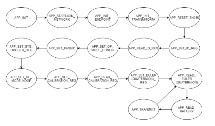
Program states
Now that we have laid out the path for communicating with sensors, let's discuss the states of the program that the program is running through.
APP_NOTHING- this state is used in cases a program needs to stop due to an error.APP_INIT- In this initialize state the boolean variables, which are deciding whether to read Euler angles or Quaternions are set up.APP_STARTJOIN_NETWORK- A must include ZigBee state. Here the coordinator (master node) is starting a PAN, while the other two ZigBee end devices join this network in this state.APP_INIT_ENDPOINT- A must include ZigBee state where the endpoint is being initialized.APP_INIT_TRANSMITDATA- A must include ZigBee state where the data structure of the message on the PAN is defined. In this case, the structure looks like this:
Payload structure
typedef struct _AppMessagePayloadEnddevice_t{ uint8_t moduleName; int32_t eulerX, eulerY, eulerZ; // all values are 1000 times int32_t quatW, quatX, quatY, quatZ; // all values are 1000 times uint32_t voltage; } PACK AppMessagePayload_t;
As the comments say, these values are multiplied by 1000 and then divided for the correct output via UART bridge interface on the PC.
APP_SET/READ_ID_REGare two states for setting and reading the ID register on the sensor to test the I2C connection.APP_SET_PAGEIDsets the page ID on the sensor to 0. This enables reading sensor data.APP_SET_OP_MODE_NDOF- here the operation mode of the sensor is set to NDOF, which is one of the fusion modes in which all three sensor signals from accelerometer, magnetometer and gyroscope are present with an absolute orientation of the fusion data output. This state is needed because the default operation mode after the power up of the sensor is theCONFIGMODEand sensors are not yet powered in this mode.APP_SET/READ_CALIBRATION_REGare states in which the calibration of the sensor modules is activated. The sensor data for our application was calibrated enough as is, but with this mode the data is even more correct.APP_READ_EULER/QUATERNION- in these states the sensor data is read, multiplied with 1000 and then later saved asint32_tvariables.APP_READ_BATTERYas the name suggest reads the current voltage of the battery pack attached to the ZigBee end-devices. Coordinator is attached via the UART bridge to the PC, powering itself in that way.APP_TRANSMIT- initialized packets with sensor data from eitherAPP_READ_EULERorAPP_READ_QUATERNIONare sent over PAN to the coordinator.
Read/write sensor in practice
As already mentioned, in order to read a register that has sensor data stored, the register itself needs to be selected by doing an I2C write first. For this reason, the APP_SET... states exist.
Below is the code for setting a Quaternion start register for reading. This is nothing we have not explained yet. In the case of failure the program goes directly into APP_NOTHING state.
APP_SET_QUATERNION_REG State
case APP_SET_QUATERNION_REG: if(debugMode){ printLineToUSART("------------------------------"); printLineToUSART("STATE: APP_SET_QUAT_REG"); } if(-1 == writeBno055(1, QUATERNION_DATA_W_LSB_ADDR, 0x00)){ printLineToUSART(ERROR_SEL_REG_QUA); appstate=APP_NOTHING; SYS_PostTask(APL_TASK_ID); } appstate=APP_READ_QUATERNION; SYS_PostTask(APL_TASK_ID); break;
Now, the actual reading of the data stored in Quaternion registers can begin. In this case, 8 bytes of data will be read (8 registers) and then stored in 4 int16_t variables w, x, y, z. The data needs to be scaled to the correct range and multiplied with 1000 to preserve the 3 floating point digits.
APP_READ_QUATERNION State
case APP_READ_QUATERNION: if(debugMode){ printLineToUSART("--------------------------------"); printLineToUSART("STATE: APP_READ_QUATERNION"); } readBno055(8, readDataQ); { int16_t w, x, y, z; w = x = y = z = 0; w = (((uint16_t)readDataQ[1]) << 8 ) | ((uint16_t)readDataQ[0]); x = (((uint16_t)readDataQ[3]) << 8 ) | ((uint16_t)readDataQ[2]); y = (((uint16_t)readDataQ[5]) << 8 ) | ((uint16_t)readDataQ[4]); z = (((uint16_t)readDataQ[7]) << 8 ) | ((uint16_t)readDataQ[6]); // convert the values to appropriate range const double scale = (1.0/(1<<14))*DEC_POINT_PRECISION; // (1/(1<<14))*1000 int32_t wThousand = (w*scale); int32_t xThousand = (x*scale); int32_t yThousand = (y*scale); int32_t zThousand = (z*scale); voltage = (float)adcData * 0.00625*VOLTAGE_RATIO; // 0.00625 = 1.6 (Referenzspannung) / 256 (2 hoch 8 bit Auflösung) uint32_t intVoltage=(uint16_t)(voltage*DEC_POINT_PRECISION); // store these values in network payload message networkMessagePayload=(AppMessagePayload_t){ .moduleName=0x02, .quatW=wThousand, .quatX=xThousand, .quatY=yThousand, .quatZ=zThousand, .voltage=intVoltage }; float floatW=(float)wThousand; float floatX=(float)xThousand; float floatY=(float)yThousand; float floatZ=(float)zThousand; floatW=floatW/DEC_POINT_PRECISION; floatX=floatX/DEC_POINT_PRECISION; floatY=floatY/DEC_POINT_PRECISION; floatZ=floatZ/DEC_POINT_PRECISION; printDoubleToUSART(floatW); printTextToUSART(", "); printDoubleToUSART(floatX); printTextToUSART(", "); printDoubleToUSART(floatY); printTextToUSART(", "); printDoubleToUSART(floatZ); printTextToUSART(", "); printDoubleToUSART(voltage); printLineToUSART(" "); } appstate = APP_READ_BATTERY; SYS_PostTask(APL_TASK_ID); break;
Now you are able to read/write into sensor registers and also parse the data output from the BNO055 smart sensor.
That's it for the backend part, now let's see the frontend of the program.
VPython UI
Since the mandatory requirement was to visualize two ZigBee end-devices moving according to the sensor readings on the screen, let's see how that turned out to be.
This part was done by my teammate and I did not contribute to development of this interface. This is how the interface looks like:
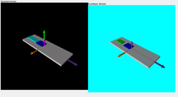
Both of the scenes are parsing live feeds from the sensors and boards are being rotated if they are rotated in real life.
This gave me an idea to make a game out of it and present it in the final demo for the project. Around the time of the project I was fascinated by maze generation algorithms which make solvable but random mazes. The dots connected and I wanted to generate mazes which are rotating and tilting based on your input from the sensors.
Next up, let's see my contribution in the visualization of the data in the form of a game.
The Marble Maze Game
The game concept is really simple; you start at a start position in one of the corners of the maze and your goal is to roll the ball to the end position marked in red on the diagonal corner of the maze. The game lacked a menu system, a game ending screen and any serious rewarding system because of the time constraint weeks before the end of the project.
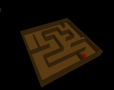
The board came in three different sizes: small (3x3 cells), medium (6x6) and large (9x9) and pictured above is the medium sized maze used for the demo.
To generate a maze, the randomized recursive depth-first search algorithm is used.
Closing thoughts
Thanks to the professor and his decent assistant we were able to learn a lot regarding wireless sensor networks and microcontroller programming during the course of the project. It also helped me motivate and lead my teammates into achieving greatness.